Command line tools (dwg2pdf, dwg2svg, dwg2bmp, etc.)Ĭlick here for a complete list of features.Very complete and extremely powerful ECMAScript (JavaScript) scripting interface.Various powerful entity selection tools.Causes: By default the creation process will be stopped after 30 minutes.

After 30 minutes the isometric creation process stops. Causes: Plumbing lines are used instead of Pipes. Construction and modification of points, lines, arcs, circles, ellipses, splines, polylines, texts, dimensions, hatches, fills, raster images Products and versions covered Issue: When trying to create an isometric drawing in AutoCAD Plant 3D, it will never been finished. When drawing pipes in AutoCAD MEP the objects always display as a single line instead of 2 lines or 3D when switching to an isometric view.The drawing axes of the isometrics intersect at an angle of 60.

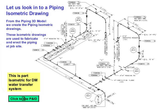
You can download QCAD today for free! Main Features A piping isometric drawing is a technical drawing that depicts a pipe spool or a complete pipeline using an isometric representation. You don't need any CAD experience to get started with QCAD immediately.

QCAD is an easy to use but powerful 2D CAD system for everyone. But what people notice most often about QCAD is its intuitive user interface. QCAD was designed with modularity, extensibility and portability in mind. Create, store, view, and share isometric drawings with AutoCAD® Isometrics WS. The source code of QCAD is released under the GPL version 3 (GPLv3), a popular Open Source license. With QCAD you can create technical drawings such as plans for buildings, interiors, mechanical parts or schematics and diagrams. These are used by fab shops to create each individual spool as dgorsman mentioned.QCAD is a free, open source application for computer aided drafting (CAD) in two dimensions (2D).

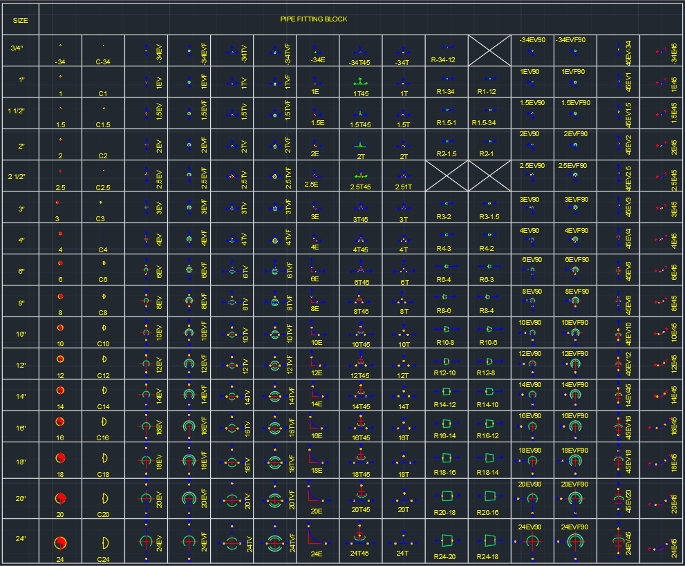
If you choose Spool drawing - you will end up with a single pipe spool per drawing based on the size criteria entered in the spool section. If you have selected "Iso drawing" - the spool section is used to define spools to be annotated within that iso, and consequently the Isos will split sheets at spool boundaries, but can contain multiple spools. New field welds can be added to the iso if you specify the "place field welds at maximum pipe length" setting. New flanges or other components will not be added - we use what is modeled, but the piping will be split at existing flanges/field welds to ensure each spool is not bigger then the size specified. Piping Isometric DWG Symbols designed just for you in AutoCAD. For example you can enter the size limitations imposed by your truck size for example to limit the spool size so that it can be transported. DWG Size: 163KB Source: AutoCAD platform 2018 and later versions. The Spools section you have highlighted in red in the image is where you adjust criteria to determine the size of a pipe spool.


 0 kommentar(er)
